ThermaLine Ice Melt Systems
Our heated panels are designed to safely eliminate snow and ice buildup before it becomes a problem.



Our heated panels are designed to safely eliminate snow and ice buildup before it becomes a problem.


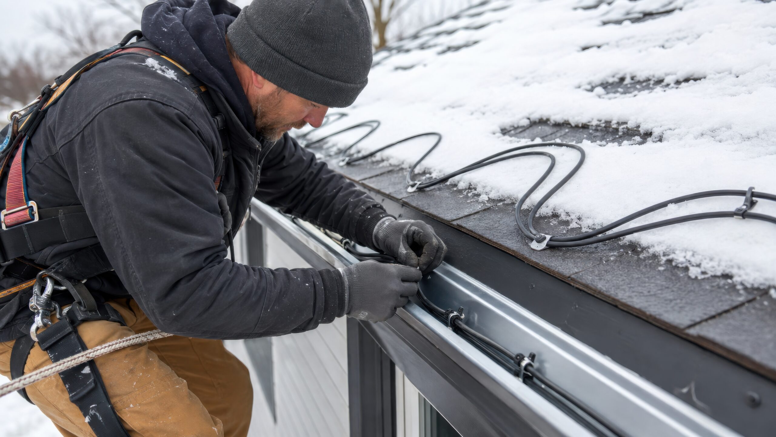
A roof deicing system fails in one of two ways. Either the equipment is wrong, or the layout is wrong. In our experience reviewing existing installations, the layout is wrong far more often, and the failure is almost always the same one: the heated area stops short of where it needed to reach, so meltwater leaves the warm zone and refreezes on cold roof a few feet later.
Layout is geometry, and the geometry is governed by the building rather than by preference. Where the exterior wall sits relative to the roof edge, how deep the overhang is, how steep the pitch is, where the valleys land, and where the water is supposed to go once it is liquid all dictate the pattern. Get those relationships right and a modest system works. Get them wrong and no amount of wattage compensates.
ThermaLine designs and manufactures roof ice melt systems to each roof’s specific configuration, which means layout is most of what we do. This guide covers the physical layout: how far coverage has to reach, how valleys and roof steps get run, how gutter runs tie into downspouts, and where circuit length caps a zone. It assumes you already understand how the cable itself behaves. If not, start with self-regulating roof heat cable for commercial buildings. Controls and sensing are a separate subject, covered in commercial roof heat cable controllers and sensors.
Before any pattern, one rule: the heated melt path must be continuous from where the snow melts to where the water leaves the building.
Every layout mistake is a violation of that single rule. Cable that heats the eave but not the gutter dumps water into a frozen trough. A heated gutter with an unheated downspout backs up as soon as the downspout plugs with ice. Coverage that stops at the exterior wall line leaves a cold band above it where water refreezes and starts a new dam higher on the roof. In each case the individual component works and the system does not, because the path is broken somewhere.
Design the path first, in one continuous line from the highest point where meltwater originates to the point of discharge, and then decide what equipment covers each segment. Doing it in the other order, component by component, is how gaps happen.
This is the most consequential dimension in the entire layout, and the one most often decided by guesswork.
Coverage is measured relative to the interior face of the exterior wall, which is roughly where the heated space ends and the unheated overhang begins. That line, not the fascia, is what matters. Above it, the roof is warmed from below by the building. Below it, the roof deck is cold on both sides, which is exactly why ice forms there.
The heated band has to extend up the slope past that line and terminate over conditioned space. Common practice in the industry is to carry coverage at least 12 inches up the slope beyond the interior wall face, and more where the roof assembly is well insulated, where the attic or plenum runs cold, or where the fall inspection showed ice forming higher than expected.
That last input is worth emphasizing. If you measured the top edge of the granule loss or staining band during a fall inspection, you have empirical evidence of how high ice actually formed on that specific building. Design to that measurement rather than to a rule of thumb.
The required slope distance is the sum of two components: the overhang, measured along the slope rather than horizontally, plus the extension past the wall line.
Two things make this larger than people expect:
Both are easy to verify on site and easy to get wrong on paper.
Traditional exposed heat tape achieves a coverage band by running the cable in a serpentine or zig-zag pattern along the eave. The base of each triangle runs along the roof edge at a fixed spacing, commonly in the range of 15 to 30 inches, and the apex height is set by the required coverage depth. The cable length required scales quickly: doubling the coverage height roughly doubles the cable, and the actual heated area is still just the line the cable occupies, with cold gaps between the legs.
Panel systems reach the same coverage band differently. ThermaLine panels run parallel to the eave, with the cable held in a three-sided raceway that presses it against the panel so heat spreads across the panel surface rather than staying on the cable line. Coverage depth is set by panel width and by how many parallel courses are installed, and the systems use roughly one-third the cable of a conventional zig-zag layout to protect an equivalent area.
The layout logic is the same either way. The required coverage band is determined by the building, and the pattern is how you fill it. What changes is the cable length, the uniformity of the heated surface, and the electrical load that follows from both.
Certain locations need more than the standard eave treatment:
Valleys concentrate water from two roof planes into one path, which makes them both the highest-volume drainage route and the most reliable place to find ice.
Run the valley from the eave upward. The valley run has to connect continuously to the eave coverage, not sit as an isolated segment. A heated valley that discharges onto an unheated eave has simply moved the dam.
Carry it far enough up. Common practice is to run the valley to roughly two thirds to three quarters of its length, and further where inspection evidence shows ice forming above that. On short valleys, run the full length. The governing question is where the water starts, not where it is convenient to stop.
Single or double runs. Wide valleys and high-volume valleys warrant a double run to establish an adequate melt path. Narrow residential-scale valleys on a small commercial building may need only a single run. ThermaValley panels are made in 1.5 inch, 2 inch and 3 inch widths in single or double cable configurations for exactly this reason, and the width selection is a layout decision rather than a product preference.
Roof steps and upper roof discharge. Where an upper roof drains onto a lower roof, the lower roof receives concentrated meltwater at a specific point and often receives sliding snow as well. That landing zone needs coverage, and it needs a defined path from the landing point to the lower roof’s drainage. This condition is frequently missed entirely because it is not an eave and not a valley, and it produces some of the worst ice accumulations on commercial buildings.
Parapet and wall transitions. Where a sloped roof meets a wall, the flashing line collects snow and holds water. Coverage along the transition, tied into the drainage path, prevents the wall detail from becoming the dam.
If there is one section of this article to act on, it is this one. Gutter and downspout continuity is where more systems break than anywhere else.
One continuous run, gutter into downspout. The gutter run and the downspout drop should form a single uninterrupted heated path. A separate gutter zone and downspout zone that are controlled independently, or that are installed by different trades at different times, will eventually be out of step, and the downspout is the half that gets skipped.
The downspout run has to reach the discharge point. Not the top of the downspout. Not partway down. The cable has to extend the full length of the downspout to where the water actually exits, whether that is grade, a splash block, a boot, or an underground connection. A downspout that is heated for its upper two thirds freezes at the bottom third and blocks just as completely.
Support the downspout cable. Cable hanging free in a downspout can be damaged, can bunch at the bottom, and can be pulled out by ice movement. It should be supported so it stays positioned through the full drop.
Watch the transitions. Gutter outlets, elbows, offsets and kick-outs are where ice forms first because the cross-section changes. These points need positive heat continuity, not a cable that bridges past them.
Heat the gutter itself, not just the water in it. ThermaGutter panels attach to the inside of the gutter with commercial-grade adhesive and distribute heat through the gutter channel via the raceway rather than relying on a single cable lying in the trough. The panels are made in 1.5 inch widths to suit different gutter profiles. Why heated gutters matter to the whole drainage picture is covered in why commercial heated gutter systems matter for winter drainage.
The transition from roof surface to open air is a short distance where a great deal goes wrong.
Drip edge and eave metal. Water has to be carried past the edge of the roofing and released, either into the gutter or clear of the fascia. If the melt path ends slightly short of the drip edge, water reaches cold metal and freezes there, building the icicle mass that eventually pulls the gutter down. Coverage should carry through the edge detail. On metal roofs, ThermaDrip is the low-profile application for the metal roof edge, and metal assembly detailing generally is covered under metal roofing.
Scuppers and through-wall drains. A scupper is a hole in a cold wall, which makes it an efficient freezing device. The heated path needs to run through the scupper opening and continue past the exterior wall face to the point of discharge, including any conductor head or downspout below. Heating the roof side of a scupper while the through-wall sleeve stays frozen accomplishes nothing.
Overflow provisions. Overflow scuppers and overflow drains are life safety devices that exist for the case where the primary drainage is blocked. If the primary blocks because of ice, the overflow is being asked to work in exactly the conditions that will freeze it too. Whether overflows are heated is a design decision worth making deliberately rather than by omission.
Internal drains on low-slope roofs are their own subject, with drain bowl behavior, ponding and refreeze patterns that do not apply to pitched roofs. We cover them in flat roof ice melt systems for commercial buildings.
Layout is not purely a roof geometry exercise. The electrical limits will constrain your zones, and discovering that during installation rather than during design is expensive.
The zone size is capped by whichever of these binds first:
Practical layout consequences:
Long eaves become multiple zones. A continuous 400 foot eave is not one circuit. Plan the break points deliberately, at natural boundaries rather than wherever the cable happens to run out, and make sure the break does not fall at a corner, a valley discharge, or a downspout drop.
Zone boundaries should follow drainage, not the drawing grid. A zone should contain a complete melt path. Splitting a path across two circuits means that if one trips, the other is heating water that has nowhere to go.
Higher voltage buys longer runs. Where the building has 208 to 277 volt service available at the roof, runs can be substantially longer than on 120 volts, which reduces the number of zones and the panel space required. This is worth resolving early because it affects the whole layout.
Leave margin. Designing to the exact published maximum circuit length leaves nothing for field conditions, and field conditions always add length.
Load calculation, panel siting and how zones are staged are covered with the rest of the controls discussion in the controller and sensor guide linked at the top of this article.
| Roof element | Coverage rule | Most common layout error |
|---|---|---|
| Eave and overhang | Full overhang measured along the slope, plus at least 12 inches past the interior wall face, more where evidence shows higher ice | Measuring from the fascia instead of the wall line, or from a plan view without correcting for pitch |
| Valley | Continuous from the eave run upward, commonly two thirds to three quarters of valley length | Treating the valley as an isolated segment not tied into the eave coverage |
| Roof step or upper roof discharge | Coverage at the landing zone plus a defined path to drainage | Omitted entirely because it is neither an eave nor a valley |
| Wall and parapet transition | Along the flashing line, tied into the drainage path | Left unheated, so the transition becomes the dam |
| Gutter | Full run, continuous with the downspout | Gutter heated, downspout not |
| Downspout | Full length to the actual discharge point | Cable stops partway down or is unsupported and bunches |
| Drip edge and roof edge metal | Carried through the edge so water is released clear | Melt path ends short of the edge, building icicles on cold metal |
| Scupper | Through the opening and past the exterior wall face to discharge | Roof side heated, through-wall sleeve frozen |
| Overflow drainage | Deliberate decision, documented either way | Never considered |
| Zone boundaries | Follow complete drainage paths, sized within circuit limits | Split mid-path, so a single trip disables a whole route |
If you are evaluating a proposal rather than drawing one, these questions surface most problems quickly:
A proposal that answers these confidently is generally sound. A proposal that quotes a total footage and a wattage without a marked-up roof plan should not be evaluated at all until there is one.
The relationship between how a system is laid out and how the building performs over its life, including the lifecycle argument for doing this properly, is covered in how commercial roof ice melt system design impacts long-term building performance.
Far enough to cover the entire overhang, measured along the slope rather than horizontally, plus at least 12 inches up the slope past the interior face of the exterior wall so the melt path terminates over heated space. Deep overhangs, steep pitches, well insulated assemblies and evidence of ice forming higher on the roof all increase the required depth.
Traditional zig-zag layouts space the base of each triangle along the eave, commonly in the range of 15 to 30 inches, with apex height set by the required coverage depth. Panel systems that run parallel to the eave set coverage depth by panel width and the number of parallel courses instead, which reaches the same band with substantially less cable.
Typically two thirds to three quarters of the valley length, and the full length on short valleys, with the run tied continuously into the eave coverage below it. Where inspection evidence shows ice forming higher in the valley, extend to match the evidence rather than the rule.
Yes, to the actual point of discharge. A downspout heated only partway freezes at the unheated portion and blocks completely, which backs water up into the gutter and onto the roof edge. The cable should also be supported so it stays positioned through the full drop rather than bunching at the bottom.
It depends on the cable’s output rating, the supply voltage, bus wire gauge, breaker size and the minimum start-up temperature the design assumes. Higher voltage and warmer start-up temperatures allow longer runs. Use the manufacturer’s circuit length table for the specific product and conditions, and leave margin for field conditions rather than designing to the exact maximum.
At natural boundaries that keep each complete drainage path within a single zone, so that a single circuit trip does not leave heated water discharging into an unheated route. Avoid placing a boundary at a corner, a valley discharge or a downspout drop.
Where scuppers are the drainage path and the building has a history of ice, yes, and the heated path has to run through the scupper opening and continue past the exterior wall face to the discharge point. Heating only the roof side leaves the through-wall sleeve to freeze, which blocks the drainage just as effectively.
Layout is not complicated, but it is unforgiving. The systems that work are the ones where someone traced a continuous line from the top of the ice-forming area to the point where water leaves the building, checked that the line was heated at every inch of its length, and then sized the zones so the electrical limits did not force a break in the middle of it.
If you are marking up a roof plan or reviewing a contractor’s proposal and want a second set of eyes, contact ThermaLine with your roof plan, elevations and drainage details. Systems are built to each roof’s specific design, and our product guides show how eaves, valleys, gutters, flashings and roof edges are detailed in practice.