ThermaLine Ice Melt Systems
Our heated panels are designed to safely eliminate snow and ice buildup before it becomes a problem.



Our heated panels are designed to safely eliminate snow and ice buildup before it becomes a problem.


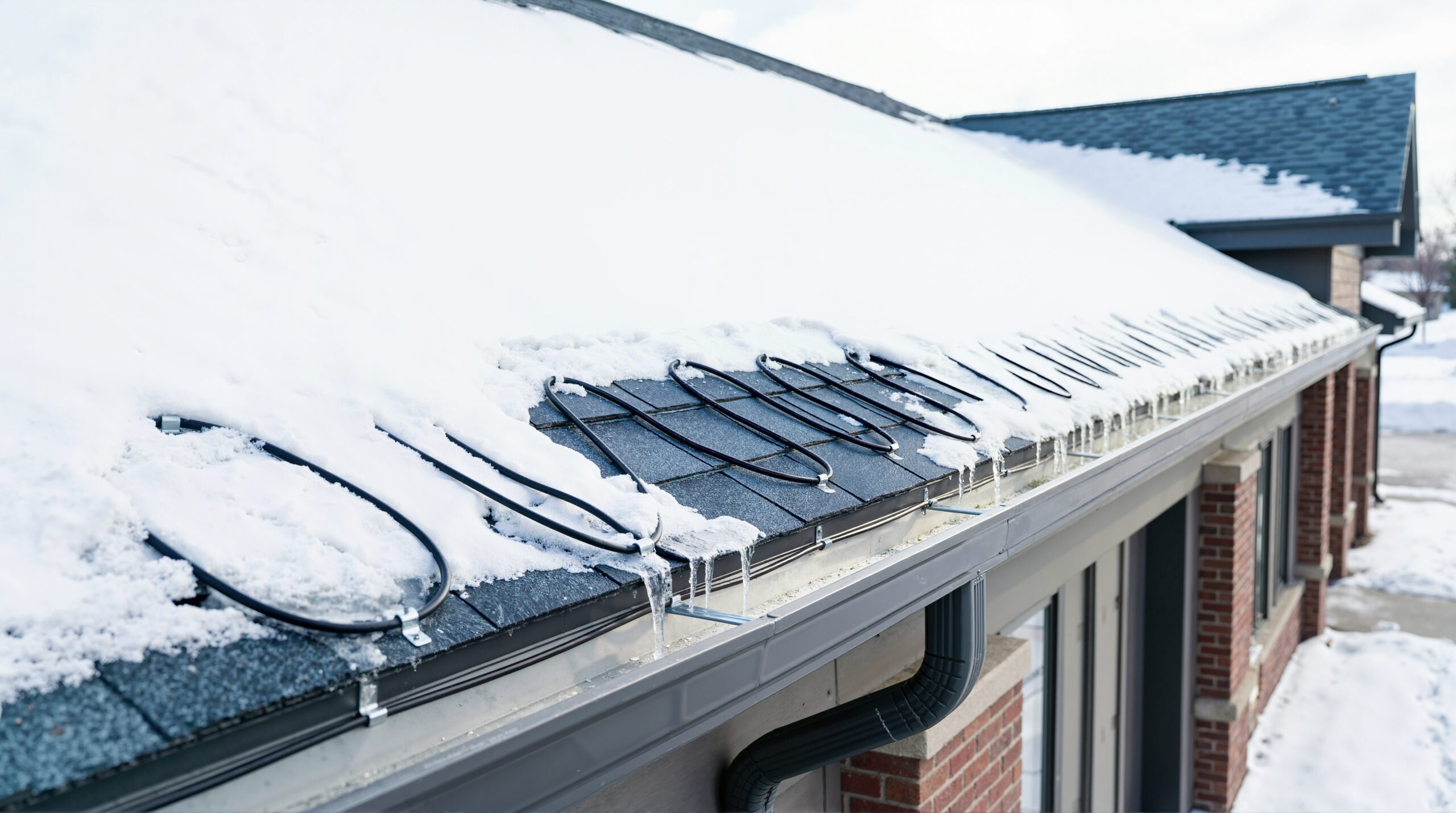
Most specifications for roof deicing name a wattage per foot and stop there. That single number tells you almost nothing about how the cable will behave on a roof in February, because self-regulating heat cable does not produce a fixed output. It produces different output in different places along the same run, at the same moment, and that behavior is the entire point of the technology.
Understanding why matters when you are comparing bids, reviewing a submittal, or writing a specification that has to survive engineering review. It also explains several things that look like contradictions on a datasheet: why a cable rated at a given wattage rarely draws that wattage, why the breaker has to be sized for a condition that lasts a few minutes, and why maximum circuit length changes depending on how cold it is when the system starts.
ThermaLine manufactures roof ice melt panels built around UL-listed self-regulating heat trace cable, so this is written from the perspective of people who spend their time on how the cable behaves once it is on a roof. This article covers the technology itself. It does not cover layout, which is the subject of our guide to commercial roof heat cable layout and coverage patterns, or controls, which we address in commercial roof heat cable controllers and sensors. If you are comparing this technology against traditional exposed heat tape as a category, that comparison lives in commercial roof deicing systems versus traditional heat tape.
Self-regulating heat cable is a parallel circuit device. Two parallel copper bus wires run the length of the cable, and between them sits a conductive polymer core. Current does not travel along the cable from one end to the other the way it does in a resistance heater. It travels across the polymer, from one bus wire to the other, at every point along the run.
That construction is what makes everything else possible.
The core is a polymer matrix loaded with conductive carbon particles. Those particles form microscopic conductive pathways between the two bus wires, and current crossing those pathways generates heat.
Here is the behavior that gives the technology its name. As the polymer warms, it expands. That expansion pulls the carbon particles slightly further apart and breaks a proportion of the conductive pathways. Fewer pathways means higher electrical resistance, and higher resistance means less current crosses at that point, which means less heat. As the polymer cools, it contracts, pathways reconnect, resistance falls, and output rises again.
There is no sensor in this process and no control logic. The material itself responds to its own temperature, continuously, at every point along its length. It is a physical property, not a feature.
Two practical consequences follow immediately. The cable cannot overheat itself into failure the way a fixed-output resistance element can, because rising temperature suppresses its own output. And the cable will never deliver its nameplate wattage across a whole run under real conditions, because parts of that run will always be warmer than the rating temperature.
Because each point on the cable regulates independently, a single continuous run can be producing very different output in different places at the same instant.
Picture a run that crosses a section of roof edge packed with snow, then a section that is clear and exposed to sun, then a gutter run holding meltwater, then a downspout drop shaded by the building. Four different local temperatures, four different output levels, one cable, no zoning required. The cold, wet, ice-loaded sections draw the most power. The warm, clear sections throttle themselves down toward a low idle.
This is the single most useful property of the technology on a roof, because roof conditions are never uniform. Sun exposure, snow depth, wind scour, shading from parapets and rooftop units, and the building’s own heat loss all vary across an eave. A fixed-output cable heats all of that identically. A self-regulating cable concentrates its output where ice is actually forming.
It is also why the wattage rating on a datasheet needs to be read carefully. That figure is nominal output at a specified reference temperature, and it is a comparison point, not a prediction of what the system will draw. Actual consumption depends on ambient conditions, run configuration and how the system is controlled, which we cover in how much energy commercial roof heat cable systems use in winter.
The construction sequence matters because most of it is required by code or by the environment, and a specification that omits a layer is inviting a substitution.
Bus wires. Two parallel stranded copper conductors, sized by gauge. Gauge affects allowable circuit length, because voltage drop along the bus wires is what ultimately limits how long a run can be.
Conductive polymer core. Extruded over and between the bus wires. This is the heating element and the regulating element at once.
Primary insulation or inner jacket. Typically a polyolefin, providing dielectric insulation over the core.
Metallic braid. A tinned copper braid over the inner jacket. This serves two functions that are both essential. It provides the equipment grounding path, which electrical code requires for heating cable of this type, and it provides mechanical protection against crushing and abrasion. A cable without a braid is not appropriate for this application, and its absence should be treated as a specification failure rather than a cost option.
Outer jacket. An overjacket for environmental protection. Polyolefin is standard for roof deicing service. Fluoropolymer jackets exist for chemically aggressive or higher-temperature environments and are generally unnecessary on a roof unless there is a specific exposure to address.
When you are reviewing a submittal, the braid and the outer jacket are the two items most likely to differ from what was specified, and both affect service life.
Because the circuit is parallel rather than series, the cable can be cut to length in the field. Removing three feet from a run does not change the output per foot of what remains, it simply removes three feet of heater. This is why self-regulating cable is practical for real buildings, where no two eaves are the same length and field conditions rarely match the drawing exactly.
Two important qualifications:
Terminations and splices are engineered components. The ability to cut the cable does not mean the ends can be handled casually. End seals, power connections and splices must use kits approved for the specific cable, correctly installed, and sealed against moisture. Water intrusion at a termination is one of the most common causes of premature failure and of ground-fault trips, and it is almost always an installation defect rather than a product defect.
Cutting does not change circuit length limits. Shortening a run gives you margin. Extending one beyond the manufacturer’s maximum does not become acceptable because the cable is cuttable.
The overlap question comes up constantly, particularly at downspout drops, gutter outlets and valley transitions where runs converge. Self-regulating cable can generally cross or contact itself without creating a hot spot, because each point suppresses its own output as it warms. This is a genuine and significant advantage over fixed-output cable, which can fail where it overlaps. It is still worth confirming against the specific product’s installation instructions, because permissible practice varies by manufacturer and by cable rating, and the listing conditions govern.
This is the specification detail most often missed, and it produces nuisance tripping on otherwise well-designed systems.
Self-regulating cable draws substantially more current when it is cold than when it has reached operating temperature. A run energized at low ambient temperature presents a much lower resistance than the same run once warm, so inrush current at startup can be several times the steady-state figure. It settles within minutes, but the breaker has to survive those minutes.
What this means for the design:
If a system trips on startup during the first cold snap, this is the first thing to check, and it is a design issue rather than a defect.
Maximum circuit length is not a single number, and treating it as one is a common source of field problems. It is a function of:
Manufacturer tables are authoritative here, and they should be part of the submittal rather than referenced in passing. Where a run exceeds the limit, the answer is to split it into additional circuits, which has implications for panel space and load calculation.
Three requirements belong in any specification for commercial roof deicing, and all three should be verified against documentation rather than accepted on a datasheet claim.
The right listing for the right application. Confirm that the product carries a UL listing that covers roof and gutter deicing specifically, rather than a general industrial heat tracing listing. Ask for the listing documentation. A UL listing means the product has been tested by Underwriters Laboratories against nationally recognized safety standards for that application, and the application matters as much as the mark.
Grounded metallic covering. The braid described above is not optional. Electrical code requires a grounded metallic sheath or braid on heating cable of this type, and it must be properly bonded at terminations.
Ground-fault protection of equipment. NEC Article 426 governs fixed outdoor electric deicing and snow-melting equipment, and it requires ground-fault protection of equipment for these systems. This is not the same device as the personnel-protection GFCI used on receptacles. It is equipment-level protection, typically integrated into the deicing control panel or provided as a dedicated breaker, and set at a trip threshold appropriate to heating cable. Confirm which code edition your jurisdiction has adopted, since requirements are refined between cycles.
A useful practice when reviewing submittals: require the listing card, the manufacturer’s circuit length table for the specified voltage and start-up temperature, the termination kit part numbers, and the GFEP device specification. If any of the four is missing, the submittal is incomplete regardless of how detailed the rest of it looks.
ThermaLine systems are UL listed and compliant with NEC Article 426 requirements for roof deicing, and we can supply that documentation for review during specification or approval.
Self-regulating cores age. Over years of thermal cycling, the polymer matrix gradually changes and output declines somewhat from new. This is normal, well understood, and slow, but it means the cable is a serviceable component rather than a permanent one. Planning for eventual cable replacement is part of designing the system properly, not an admission of weakness.
In practice, the failures that occur early are almost never the polymer. They are:
This is where the difference between exposed cable and cable held in a protective panel raceway becomes concrete. ThermaLine’s panels enclose the cable in a three-sided raceway that compresses it against the panel, which protects it from mechanical damage and weather exposure while improving heat transfer into the panel surface. It also means cable service can be performed without removing the panels or disturbing the roof. Cable is typically replaced on roughly a 10 year interval, and the systems carry a 10 year product warranty.
Self-regulating cable is the right technology for most commercial roof deicing, but it is not the only one, and it is worth knowing where the alternatives still make sense. Constant wattage parallel cable produces a fixed output per foot regardless of temperature, which is a disadvantage on a roof with widely varying conditions but an advantage where predictable, uniform output is required. It also supports longer circuit runs than comparable self-regulating cable in some configurations, which occasionally matters on very large single-zone applications. The tradeoffs are real: it cannot be overlapped, it does not throttle down in warm or dry areas, and it consumes at its rated output whenever it is energized. Series resistance cable, which is cut to a fixed length at the factory and cannot be shortened in the field, still appears in some applications but is generally poorly suited to roof work where field conditions rarely match drawings. For the great majority of commercial roof, gutter and downspout deicing, self-regulating cable’s ability to respond point by point to actual conditions is the deciding advantage.
A final point that specifications routinely omit. The cable is only half the system. How it is held against the roof determines how much of its output reaches the surface that needs to be warm.
Cable lying loose on a roof surface, or clipped in a zig-zag pattern, loses a significant portion of its output to the air around it. Cable held in firm contact with a conductive panel transfers heat into that panel, which spreads it across a defined melt path. This is why ThermaLine panels run parallel to the eave rather than in a zig-zag, and why the raceway compresses the cable against the panel material. The systems use roughly one-third the cable of conventional zig-zag layouts to protect an equivalent roof area, and the company reports energy savings of up to 65 percent compared with traditional exposed heat tape.
Panels are manufactured in copper, aluminum or steel and install with commercial-grade adhesive without penetrating the roof deck, and each system is built to the specific roof’s design. The product range covers eaves, valleys, flashings, gutters, drip edges, metal roof seams and low-slope roof areas, and the product guides show how each application is detailed.
Two parallel copper bus wires are separated by a conductive polymer core loaded with carbon particles. Current crosses the polymer between the bus wires and generates heat. As the polymer warms it expands, breaking conductive pathways and raising resistance, which reduces output at that point. As it cools, it contracts and output rises. Every point along the cable regulates itself independently with no sensor or control involved.
Yes. Because it is a parallel circuit, cutting it removes heater length without changing the output per foot of the remainder, which is why it suits real buildings where run lengths vary. Terminations, splices and end seals must use kits approved for the specific cable and be sealed properly, since moisture intrusion at these points is the most common cause of premature failure.
Generally yes, because each point suppresses its own output as it warms, so an overlap does not create a runaway hot spot the way it can with fixed-output cable. This matters at downspout drops and valley transitions where runs converge. Always confirm against the specific product’s installation instructions, since permissible practice varies by manufacturer and the listing conditions govern.
Because it draws significantly more current when cold than when warm. Inrush at cold start can be several times the steady-state figure and lasts a few minutes. Overcurrent protection must be selected for that cold-start condition, using the manufacturer’s guidance and the coldest expected energization temperature as a design input.
Cable output rating, supply voltage, bus wire gauge, breaker size and the minimum start-up temperature. Higher voltage supports longer runs, and colder start-up temperatures shorten them. Use the manufacturer’s circuit length table for the specific voltage and start-up temperature rather than a general figure, and require it as part of the submittal.
Yes. NEC Article 426 covers fixed outdoor electric deicing and snow-melting equipment and requires ground-fault protection of equipment. This is equipment-level protection, distinct from a personnel GFCI, and is typically provided within the deicing control panel or as a dedicated breaker. The cable also requires a grounded metallic braid, properly bonded at terminations.
The polymer core gradually loses some output over years of thermal cycling, and cable is generally treated as a serviceable component replaced on roughly a 10 year interval. Most early failures are not the polymer but moisture intrusion at terminations, mechanical damage, or jacket degradation, all of which are reduced when the cable is protected in a panel raceway rather than left exposed.
Self-regulating cable varies its output point by point based on local temperature. Constant wattage cable produces a fixed output per foot whenever energized, regardless of conditions, and cannot be overlapped. Self-regulating is generally the better fit for roofs, where sun, snow depth, shading and heat loss vary across a single run, while constant wattage occasionally suits applications needing uniform predictable output or unusually long circuits.
A roof deicing specification that names a wattage per foot and a total length has described less than half of what determines whether the system works. The elements that decide performance are the listing category, the braid and jacket construction, the start-up temperature the circuit lengths were calculated against, the overcurrent protection selected for cold start, the ground-fault protection, and how firmly the cable is held against the surface it is meant to heat.
If you are writing or reviewing a specification and want the technical documentation to evaluate it properly, contact ThermaLine. We can provide listing documentation, circuit and electrical requirements, and application details for your specific roof configuration. Our FAQ also covers common operating and maintenance questions, and if you are working against a first-freeze deadline, our guide to when to install commercial roof heat cable systems before winter covers the scheduling constraints.